Video Lesson: How to Construct a Precedence Network from a Prerequisite Table
What is a Precedence Network?
A precedence network is a visual diagram used for representing the tasks required for completing a project. Arrows are used to show the dependencies of the tasks in relation to one another. The tasks are labelled on each arrow along with their individual completion times. From this the minimum completion times of the project can be found.
Precedence networks can be drawn in a variety of forms and are also known as network diagrams or nodal diagrams.
Precedence networks are used in project management in the precedence diagramming method or the activity-on-node method. They allow calculation of the minimum completion time of the whole project and the slack time for individual tasks in the project.
Precedence networks allow for a visual view of tasks listed in a prerequisite table. Nodes separate the tasks.
Here are some examples of precedence network diagrams drawn from their prerequisite tables.
Example 1
On the left is shown a prerequisite table detailing the duration of each task and the prerequisite tasks required to be completed before each task begins.
| Task | Duration | Prerequisites |
| A | 1 | – |
| B | 2 | – |
| C | 4 | – |
| D | 3 | A |
| E | 1 | B |
| F | 2 | C |
| G | 5 | C |
| H | 6 | E, F |
| I | 3 | G, H |
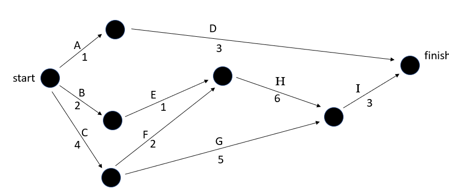
In this example, the tasks of A, B and C have no prerequisite. Therefore these tasks can be undertaken immediately and the arrows representing these tasks leave from the starting node.
Task D requires task A as a prerequisite and so, it comes out of the end of task A.
Task E requires task B as a prerequisite and so, it comes out of the end of task B.
Both tasks F and G require task C as a prerequisite. Both tasks come out of the end of task C shown with two separate arrows.
Task H requires tasks E and F and so, both arrows of task E and F must combine to the same node before task H can leave it.
Task I also requires two prerequisite tasks of G and H. Tasks G and H combine at one node and task I leaves from it.
All tasks that are not prerequisites for other tasks must end at the finish node. In this example tasks D and I must point to the finish node.
Example 2
Here is another example of a precedence network in which a dummy link is present pointing from the end of task A to the end of tasks E and F.
| Task | Duration | Prerequisites |
| A | 6 | – |
| B | 4 | A |
| C | 1 | – |
| D | 1 | A |
| E | 3 | – |
| F | 1 | C |
| G | 3 | A, E, F |
| H | 1 | B |
| I | 1 | G |
| J | 5 | D, H |
| K | 1 | I, J |
| L | 3 | B |
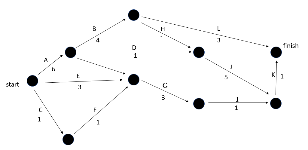
In this example tasks A, C and E have no prerequisites and can be completed immediately. These tasks leave from the starting node.
Tasks B and D both require task A and follow on from the node at the end of task A.
Task F requires task C and is drawn coming out of task C.
Task G requires tasks A, E and F. Tasks E and F can point directly into the node before G. A dummy link is used to connect the end of task A into the node before task G. The dummy link is shown more clearly in red in the image below.

The dummy link allows tasks B and D to only have task A as a prerequisite, whereas task G can have task A as a prerequisite along with tasks E and F.
Tasks H and L require task B and are shown coming out of task B.
Task I requires task G.
Task J requires tasks D and H which combine at the node before it.
Task K requires tasks I and J.
Finally, tasks K and L are not prerequisites for any other task and so, they are connected to the finish node.
How to Draw a Precedence Network Diagram
To draw a precedence network:
- First draw any tasks that have no prerequisites coming out of the start node.
- Draw nodes at the end of each task.
- Draw tasks coming out of their prerequisite tasks.
- If two or more tasks are prerequisites for another task, they must all connect to this node.
Example 1
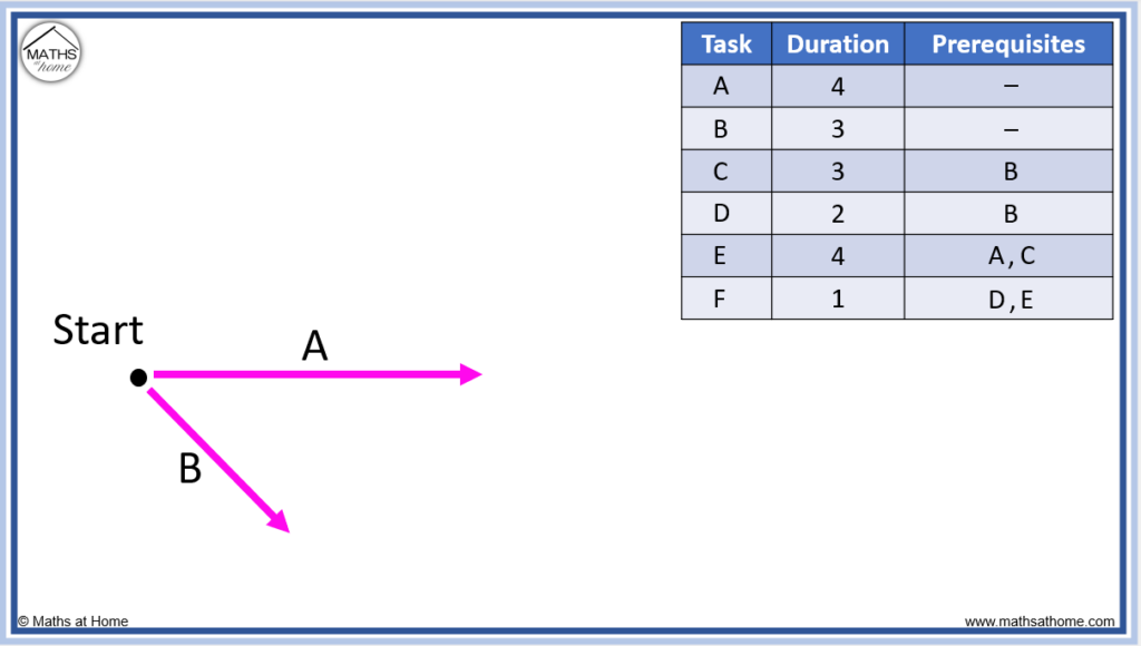
Draw the precedence network for the following prerequisite table

Step 1. Draw tasks that have no prerequisites
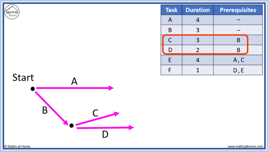
Tasks A and B have no prerequisites and so they are drawn first, coming out of the starting node.
Step 2. Draw tasks coming out of their prerequisite tasks
Tasks C and D both have task B as a prerequisite.
This means that task B must be completed before task C and D begin.
Therefore we draw tasks C and D at the end of task B.
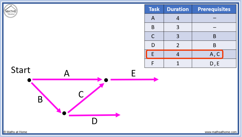
Next we can see that task E requires both tasks A and C.
If a task has multiple prerequisite tasks, these prerequisite tasks must connect at the same node.
This means that task A and C must combine together at the same node. Task E will come out of this node as seen below.
Finally, task F requires both tasks D and E.
This means that tasks D and E combine to connect to the node that task F comes out of.

Since there are no further tasks, task F connects to the finish node.
How to Find the Critical Path on a Network Diagram
To find the critical path, complete a forward scan of the network. Write the largest path to get to each node. The longest path through the network is the critical path. The length of this path is the minimum completion time.
The following three images show the development of the critical path.
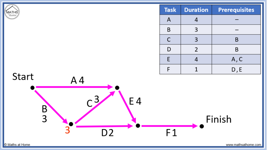
Following task B, the only way to this node is of length 3.

At the top-most node, we have a choice of task A (4 minutes) or task B then task C (3+3=6 minutes).
We write 6 minutes at this node as we always write the longest path.

To get to the next node we can travel from the node with 3 on it along task D (3+2=5 minutes) or from the node with 6 on it along task E (6+4=10).
We write the longest path of 10.
Finally, taking task F, 10+1=11 minutes.
Therefore 11 minutes is the minimum completion time.
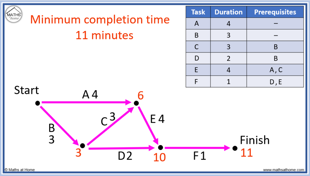
The critical path is comprised of the tasks taken from start to finish to make the minimum completion time.
The critical path is B-C-E-F.
Network Diagrams with Dummy Links
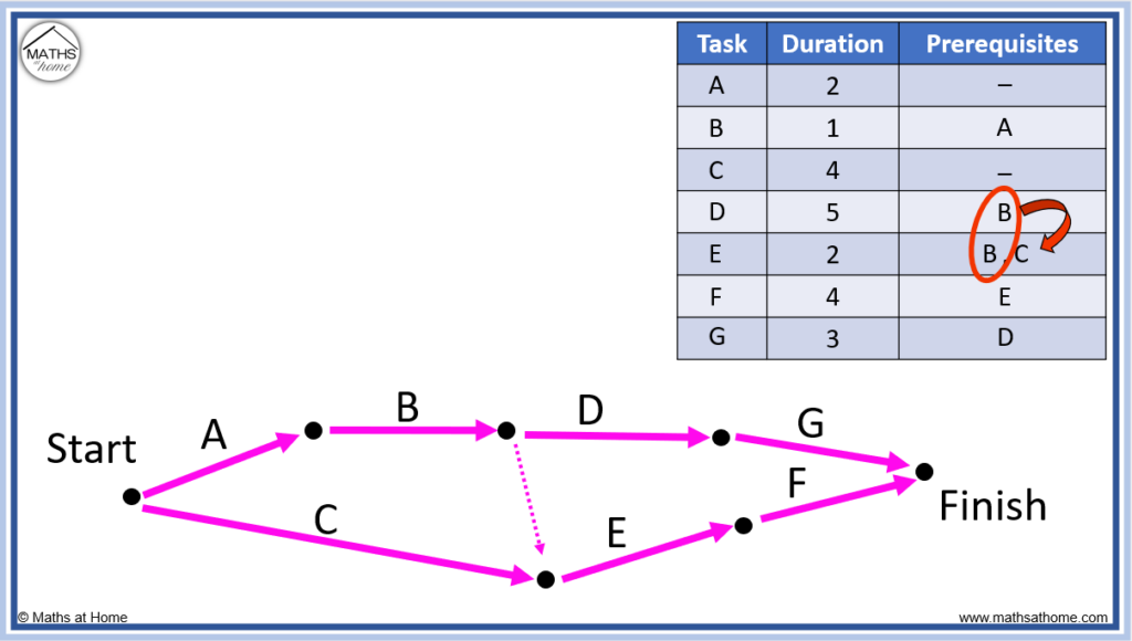
Dummy links are required when a task is a prerequisite for more than one task and one of these tasks also has another prerequisite task. Dummy links are easily identifiable in a prerequisite table when there is a repeated task letter in which one of these letters has another task letter next to it.
For example, in the table below the task B is a prerequisite for D and E.
However, task C is a prerequisite for task E but not task D.
Dummy links are always drawn from the end of the repeated task to the end of the other task that is alongside it.
Task B is repeated and task C is alongside on of them.
Therefore the dummy link must pass from the end of task B to the end of task C.
Dummy links, also known as dummy activities are not labelled on the network diagram. They do not have any numerical weighting and travelling through them adds zero to the total path length. They are simply used to connect the network according to the prerequisites.
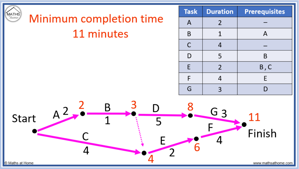
How to Find the Minimum Completion Time
The minimum completion time is the shortest time a project can be completed. It is the longest path on a network from start to finish. The minimum completion time is the sum of the times on the critical path.
For example, the critical path on the network below is A-B-D-G.
Adding the times on the critical path tells us the minimum completion time.
2 + 1 + 5 + 3 = 11 and so, the minimum completion time is 11 minutes.